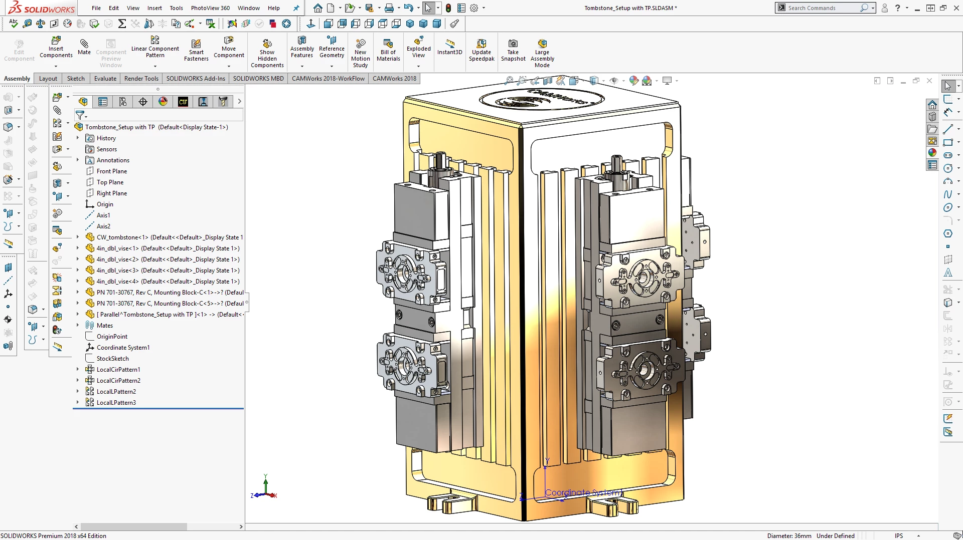
CAMWorks for SolidWorks provides CNC programmers and manufacturing engineers with a direct machining environment operating natively inside their 3D design workspace. Instead of exporting models to standalone computer-aided manufacturing applications, machinists generate toolpaths, assign cutting tools, and verify operations without ever leaving the host interface. Because the two systems share the exact same part data, any change made to a component’s geometry automatically updates the corresponding G-code. This associativity eliminates the tedious cycle of importing, translating, and reprogramming files every time a part design is revised. By keeping the entire workflow within a single window, operators avoid file format translation errors that can occur when moving STEP or IGES files between different software ecosystems.
The primary role of this add-in is to translate digital models into physical parts with minimal manual setup. By analyzing prismatic features like holes, slots, bosses, and pockets, the software applies predefined machining rules to calculate feeds, speeds, and operation sequences. This approach benefits job shops and production facilities handling frequent revisions or families of parts where consistency matters. Instead of relying entirely on manual chain selection or drawing boundaries, operators let the system identify machinable areas, allowing them to focus on optimizing fixturing, workholding, and material removal rates. Engineers can spend more time refining the physical setup on the CNC mill, selecting the best carbide grades, and ensuring proper coolant flow rather than clicking individual lines and arcs on a computer screen.
For desktop machining workflows, relying on a locally installed application ensures direct access to processing power and hardware resources necessary for calculating complex multi-axis toolpaths. While cloud-based alternatives exist, local processing handles large assemblies and intricate part data without depending on continuous internet connectivity or external server availability. Machinists retain full control over their post-processors, tool cribs, and proprietary machining databases, ensuring that sensitive manufacturing data remains securely on the shop floor. Local execution also prevents unwanted forced updates from altering the software interface or removing legacy functions in the middle of a critical production run.
Key Features
- Automatic Feature Recognition (AFR): The system scans 3D models to identify over 20 different prismatic shapes, including bosses, pockets, holes, and slots. Once identified, it automatically applies standard machining operations to these geometries, reducing the time spent manually selecting edges or sketching boundaries. This automatic detection adapts to model changes, so resizing a hole instantly recalculates the drilling cycle.
- Knowledge-Based Machining (KBM): Using the built-in Technology Database (TechDB), the software stores and applies company-specific manufacturing rules to recognized features. It automatically selects the correct cutting tools, feeds, speeds, and depths of cut based on the material properties and machine type. Operators can modify these rules to capture their shop's preferred methods, ensuring consistent programming across different operators and shifts.
- Tolerance-Based Machining (TBM): The software reads Product and Manufacturing Information (PMI) and geometric dimensioning directly from the 3D model. It then interprets surface finish annotations and dimensional tolerances to choose the correct machining strategy. For example, a tight-tolerance hole might automatically receive a center drill, drill, and ream sequence, eliminating the need to cross-reference 2D PDF drawings to determine which holes require high-precision finishing passes.
- VoluMill High-Speed Roughing: This active toolpath engine generates adaptive roughing cycles that maintain a constant chip load and material engagement angle. By avoiding sharp directional changes and full-width cuts, the system allows cutting tools to utilize their entire flute length at higher feed rates. This approach shortens the overall machining cycle time while reducing wear on both the spindle and the cutting tool.
- Associative Toolpath Updating: Because the machining data is stored inside the original design file, any alteration to the geometry triggers an automatic recalculation of the affected toolpaths. If an engineer deepens a pocket or moves a bolt hole circle, the operator does not need to start a new CAM project. The software flags the outdated operations, allowing the user to regenerate the G-code with a single command.
- Virtual Machine Simulation: Before sending code to the physical equipment, the software simulates the material removal process within a digital kinematic model of the specific CNC machine. It checks for collisions between the tool, holder, workholding fixtures, and machine components during 3-axis, 4-axis, or 5-axis operations. This visual verification prevents costly crashes on the shop floor and confirms that the part can be manufactured as programmed.
How to Install CAMWorks for SolidWorks on Windows
- Download the executable setup package from the official HCL vendor portal or an authorized reseller link.
- Verify that a compatible installation of the host CAD software is already active and licensed on the target Windows workstation.
- Launch the setup file with administrator privileges to ensure the installer has the necessary permissions to write to system directories and register the add-in.
- Follow the installation wizard prompts to accept the end-user license agreement and select the desired destination folder, typically located on the primary system drive.
- Choose the specific modules and post-processors required for your shop's machinery during the custom setup phase, omitting any unneeded machine definitions to save disk space and keep the drop-down menus uncluttered.
- Complete the installation process and launch the host CAD application.
- Open the Add-ins menu from the primary toolbar, check the box next to the newly installed CAM module to activate it, and verify that the new machining tabs appear in the command manager.
CAMWorks for SolidWorks Free vs. Paid
A basic tier of this technology is available at no additional cost for users who maintain an active subscription to the host CAD software. This included tier, often branded as SolidWorks CAM Standard, provides 2.5-axis milling capabilities and basic automatic feature recognition. If a user stops paying their annual CAD maintenance fee, access to this included CAM module is typically revoked, even if the primary CAD license is a perpetual license. This means the free tier operates effectively as a subscription benefit rather than a permanently owned utility.
For more advanced requirements, HCL Technologies offers paid commercial tiers starting with a Standard bundle and scaling up to Professional, Premium, and Ultimate packages. These paid bundles transition the software from basic 2.5-axis operations to full 3-axis surface milling, 4-axis and 5-axis simultaneous machining, and complex mill-turn operations. Moving to the paid tiers also unlocks advanced roughing engines and synchronous machining capabilities for multi-turret lathes.
The paid bundles operate on either perpetual licenses with optional annual maintenance contracts or term-based subscription models, depending on the reseller agreement. Purchasing a perpetual license for a higher tier can cost several thousand dollars upfront, with an additional yearly fee to receive software updates, bug fixes, and technical support. Specialized add-ons, such as Swiss machining modules, virtual machine simulation, or advanced nesting capabilities for sheet metal, are sold separately and can further increase the total cost of deployment. Standard pricing strictly segments advanced multi-axis functionality behind these higher paywalls, meaning shops must carefully evaluate their actual hardware capabilities before purchasing a premium software tier.
CAMWorks for SolidWorks vs. SolidCAM vs. Mastercam
SolidCAM operates within the exact same design environment, offering a very similar native workflow for users who prefer to stay inside their primary CAD interface. The main distinction lies in its proprietary iMachining technology, which many machinists prefer for its aggressive and highly optimized material removal rates in hard metals like titanium or inconel. While both systems offer feature recognition, SolidCAM often requires slightly more manual intervention during the initial setup but rewards the operator with highly efficient roughing cycles that maximize tool life and reduce heat generation at the cutting edge.
Mastercam functions as a standalone application rather than a direct add-in, requiring users to import their CAD files before programming. It relies heavily on manual chain selection and boundary definition, giving the programmer direct control over every micro-movement of the cutting tool. This manual approach makes Mastercam the preferred choice for complex 5-axis aerospace parts or intricate mold-making where automated feature recognition might misinterpret the optimal cutting strategy. Mastercam also benefits from an enormous user base, making it easier to hire operators who already know the interface.
CAMWorks for SolidWorks is the better choice for production environments dealing with families of parts, standardized features, and frequent design revisions. By leaning heavily into its Technology Database and automatic recognition, it allows shops to standardize their machining practices and reduce programming time on prismatic parts. It excels when a shop wants to embed its specific manufacturing intelligence into the software, allowing operators to generate safe, consistent G-code based on rules established by senior programmers.
Common Issues and Fixes
- Redundant or impractical toolpaths are generated after running Automatic Feature Recognition. Do not rely entirely on the automated feature tree for complex parts. Delete unnecessary operations manually, combine identical toolpaths, and ensure the correct workholding fixtures are defined so the system understands where it cannot cut.
- The standard CAM module stops functioning despite the primary CAD software remaining active. Verify the status of your annual CAD maintenance subscription. The basic CAM functionality is tied directly to an active subscription contract and will lock if the maintenance payment lapses, requiring a renewal through your reseller to restore access.
- The system predicts excessively long machining times for relatively simple prismatic parts. Check the tool crib to ensure larger end mills or face mills are available. If the database only sees small diameter tools, it will attempt to clear large pockets with inadequate cutters, drastically inflating the calculated cycle time.
- Specific G-code commands are missing or formatted incorrectly for the machine controller. Adjust the post-processor to match your specific machine's requirements. Contact your reseller for a modified post-processor file, or use the included universal post generator to edit the output formatting manually.
Version 2026 SP0 — November 2025
- Swiss Machining Environment: Introduced comprehensive support for Swiss-style sliding headstock machines, featuring a new Segmentation Manager that automatically divides long toolpaths into manageable segments to optimize stability and precision.
- Machine Kinematics in Simulation: Enhanced the Toolpath Simulation to render full machine axis motion for Milling and Turning modules, enabling visual collision detection for machine components directly within the programming interface.
- Advanced Tree Organization: Added the ability to create, rename, and manage custom folders within the Operation and Feature trees, allowing for better grouping and drag-and-drop organization of complex CAM data.
- TechDB Data Transfer: Implemented new import/export capabilities for the Technology Database, allowing users to easily migrate specific machine definitions and settings between different TechDB instances to synchronize workstations.
- Turning Enhancements: Added "Bar Break" functionality to automatically generate chamfer or radius moves that remove burrs during cutoff operations, protecting guide bushings and improving part quality.
- Stock-Aware Cutting Parameters: Enabled the definition of cutting speeds and feeds for turning inserts based specifically on the stock material assignment, streamlining the selection of optimal machining data.