LibreCAD operates as a dedicated 2D computer-aided design drafting tool built specifically to create technical blueprints, schematics, and mechanical layouts. Unlike heavy 3D modeling environments that require specialized graphics hardware, this application focuses strictly on planar geometry and precise vector drafting. Drafters, hobbyists, and laser-cutting operators use it to generate exact line work without navigating the interface overhead of a full 3D suite. It natively reads and writes the DXF file format, ensuring that the vectors generated here translate predictably into computer numerical control (CNC) routing software, laser cutters, and standard plotter drivers.
For many engineers and designers, moving from manual drafting or browser-based vector tools to a dedicated desktop application solves specific performance bottlenecks. Browser tools often struggle to render thousands of individual line segments or complex hatched areas without severe lag. By running directly on a Windows desktop environment, this software calculates geometry locally, meaning pan and zoom operations remain highly responsive even when viewing massive architectural floor plans. Users manage their work entirely offline without mandatory cloud synchronization, forced account logins, or background data uploads. The target drive handles all file storage, allowing the application to operate indefinitely on an air-gapped machine without ever requiring a network ping for license verification.
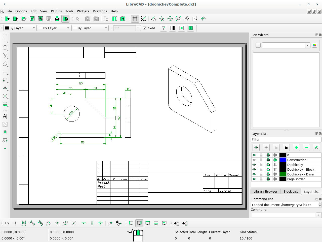
This approach primarily serves users who need exact metric or imperial layouts rather than conceptual sketches. The application relies on a strictly defined Cartesian coordinate system, requiring users to input absolute or relative coordinates, angles, and precise lengths. The user interface places toolbars for drawing, dimensioning, and modification along the left and top edges, while a highly active command-line interface anchors the bottom. Because it avoids proprietary file lockdowns, small manufacturing shops frequently deploy it to standardize their machine shop blueprints, knowing the tool will always export clean DXF data suitable for immediate physical manufacturing.
Key Features
- Feature Name: Coordinate-Based Drafting: The software relies heavily on a command-line interface located at the bottom of the screen where users type exact lengths, relative coordinates, and angles. Instead of merely dragging shapes visually, drafters input text commands like
line, specify the starting point, and enter an exact length such as@50<45to draw a 50-unit line at a 45-degree angle. This text-driven workflow ensures mechanical components align to exact mathematical tolerances rather than relying on mouse approximations. - Feature Name: Native DXF File Handling: The application natively saves, edits, and exports the DXF format, completely bypassing intermediate translation steps or third-party file converters. When a user finalizes a layout for a plasma cutter or a CNC machine, the resulting DXF file contains clean toolpaths without hidden proprietary formatting that might crash the machine's controller. It also natively exports to SVG and PDF formats for standard client review, printing, and documentation purposes.
- Feature Name: Advanced Object Snapping: Users control exactly where new lines begin and end by toggling snap behaviors through the lower toolbar buttons. Available options include snapping to line endpoints, midpoints, intersections, circle centers, and visible grid points. Activating "Snap to Entity" guarantees that a newly drawn geometric shape perfectly touches an existing line, preventing the microscopic gaps that cause toolpath errors during physical manufacturing.
- Feature Name: Layer Management System: Complex layouts are organized through a dedicated Layer List dock, allowing users to separate electrical schematics, plumbing lines, and structural walls into distinct categories. Each layer supports independent colors, line weights, and line types, such as assigning a dashed blue line to the electrical layer and a solid black line to the structural layer. Drafters can temporarily hide or lock specific layers to avoid accidentally modifying a completed section while continuing work on the rest of the blueprint.
- Feature Name: Customizable Hatching and Dimensions: Adding manufacturing notes and material indicators is handled through dedicated dimension and hatch tools found in the main toolbar. Users apply standard isometric or cross-hatching to indicate cut cross-sections or specific material types like steel, wood, or concrete. The dimensioning tools automatically measure the distance between two clicked points and generate standard architectural or engineering dimension lines with customizable text heights, spacing, and arrow styles.
- Feature Name: Block Creation and Insertion: To avoid redrawing identical components, users define specific geometry groupings as reusable Blocks via the Block List dock. A drawn window outline, a specific screw thread, or an electrical symbol can be saved as a Block and inserted dozens of times across the main drawing area. Modifying the master Block immediately updates all instances of that shape throughout the entire file, reducing repetitive drafting tasks and maintaining visual consistency.
- Feature Name: Modification and Transformation Tools: Users manipulate existing geometry using a suite of modification commands such as Move, Copy, Rotate, Scale, and Mirror. Selecting the Mirror tool allows a drafter to draw exactly one half of a symmetrical mechanical part and reflect it across a defined axis to complete the shape. The Fillet and Chamfer tools automatically round off or bevel sharp corners to exact radiuses, which is a strictly required step when designing physical objects meant for safe handling.
How to Install LibreCAD on Windows
- Download the official Windows installer package from the project's main repository or official release page, ensuring you retrieve the standard executable file rather than source code archives.
- Locate the downloaded executable in your local Windows Downloads directory and double-click the file to launch the setup wizard.
- Review the GNU General Public License terms displayed in the first prompt, then click the "I Agree" button to advance to the destination folder selection screen.
- Leave the default installation path set to
C:Program Files (x86)LibreCADor select a different local drive if your primary system partition lacks space or has strict write restrictions. - Choose whether to create a desktop shortcut and a standard Start Menu folder during the component selection step to make launching the application easier later.
- Click the "Install" button to extract the application binaries, Qt framework dependencies, and default font files to your system drive, which completes entirely offline without background downloads.
- Click "Finish" to close the setup wizard, allowing you to launch the application directly from the Start Menu without creating an account or activating a software license.
- On the first launch, the software will present a standard "Welcome" dialog asking you to set the Default Unit (such as Millimeters or Inches) and the default GUI Language, which ensures your coordinate inputs scale correctly.
LibreCAD Free vs. Paid
LibreCAD is entirely free to download, install, and deploy for personal, educational, and commercial use. The application is developed strictly as an open-source project and is distributed under the GNU General Public License version 2 (GPLv2). Because the software is maintained by a volunteer community and funded strictly through optional donations, there are no pricing tiers, pro versions, or hidden enterprise licenses. Every drawing tool, layer function, and export format is unlocked immediately upon installation.
Users transitioning from commercial drafting environments will immediately notice the complete absence of subscription checks, trial watermarks, or mandatory cloud logins. The application does not restrict the number of files you can save, limit the physical dimensions of the blueprints, or cap the number of DXF exports a user can execute in a day. Small manufacturing businesses frequently install the software across multiple workstations on the shop floor without tracking seat counts, managing license servers, or paying annual renewal fees.
The business model relies entirely on open-source collaboration and voluntary community involvement. Advanced users who need specific functionality can legally modify the source code themselves, while general users benefit from the community's ongoing bug fixes and feature merges. Because there is no paid tier or corporate backing, official technical support relies entirely on community forums, user wikis, and GitHub issue trackers rather than a dedicated commercial customer service hotline.
LibreCAD vs. AutoCAD LT vs. QCAD
AutoCAD LT represents the strict commercial standard for 2D drafting, offering highly advanced dynamic blocks, native DWG file support, and an interface familiar to nearly all professional engineering firms. Users operating within large architectural supply chains or handling complex DWG files sent by contractors generally require AutoCAD LT to ensure strict visual fidelity and file compatibility across multiple offices. However, it requires a significant annual subscription fee, mandatory account sign-ins, and heavier desktop system resources to operate effectively.
QCAD serves as another prominent 2D CAD application, sharing some historical source code roots with LibreCAD but functioning under a completely different development and distribution model. QCAD provides a highly polished user interface, frequent application updates, and stronger DWG file handling through its proprietary add-ons. While QCAD offers a free community edition, accessing its most advanced DWG import/export tools, newer rendering features, and professional support requires purchasing a commercial QCAD Professional license.
LibreCAD is the better fit for users who strictly require a permanent, zero-cost desktop application and primarily work with DXF files. Because it is completely unencumbered by commercial up-sells or artificial tier limits, it remains an excellent choice for hobbyists, independent CNC operators, and small machine shops needing to draft accurate mechanical parts for laser cutting. It completely avoids the subscription burden of AutoCAD LT and the paid-tier structure of QCAD, making it ideal for environments where straightforward 2D geometry is the only true requirement.
Common Issues and Fixes
- Problem description: Lines disappear or show incorrect thickness when viewing the drawing on screen. This usually happens because "Draft Mode" is toggled on, which forces all lines to render at a strict 0-pixel width to improve rendering speed on large, complex files. Click the "View" menu at the top of the interface and uncheck "Draft" to restore the actual line weights configured in your layer settings.
- Problem description: The Trim tool fails to cut segments of a drawn rectangle. The default rectangle tool creates a single, continuous polyline entity rather than four separate lines, and the standard Trim command cannot process a closed polyline correctly. Select the rectangle, type
explodeinto the command line, and hit Enter to break the shape into four individual line segments that can be trimmed normally. - Problem description: Exported PDF files appear completely blank or mostly empty. This occurs when the drawing objects are located far outside the defined print area or the print scale is set to a mathematically incorrect ratio. Before exporting the file, click "File" then "Print Preview," use the "Center to Page" button, and manually adjust the drawing scale ratio so the geometry physically fits within the white page border shown on the screen.
- Problem description: Imported DWG files fail to open or display missing geometric elements. The application relies primarily on the DXF format, and its native DWG support is highly limited due to the proprietary nature of standard DWG files. To fix this, ask the original file creator to export the file as an older DXF format, or process the DWG through a standalone file converter before attempting to import it.
- Problem description: Command line inputs nest incorrectly, resulting in drawn lines snapping to a length of exactly one unit. If you type a new line command before fully escaping the previous line command, the software's command line can glitch and reset the length value to 1 unit. Always press the ESC key to completely exit the active drafting tool before typing a new command to ensure accurate coordinate input and intended line lengths.
Version 2.2.1.3 — January 2026
- Added a new global keyboard shortcut (Shift+Spacebar) to improve workflow efficiency.
- Updated dialog text handling to default to Unicode fonts, enhancing text rendering compatibility.
- Improved application stability by disabling the PenWizard feature by default.
- Fixed a validation issue affecting loop operations to ensure smoother geometry processing.
- Resolved an issue with the
duplicateLayerEntity()function that caused errors during layer operations. - Corrected Qt plugin folder paths for aarch64 AppImage builds, ensuring better Linux ARM support.
- Addressed build system errors to restore successful compilation on Windows platforms.
- Performed internal code cleanup on action handlers to maintain long-term code health.