All rights reserved © 2026
If your week swings between new injection molds, last‑minute die changes, and electrodes that should have been on the machine yesterday, Cimatron 2024 is the place where scattered CAD files turn into one tooling workflow. It keeps mold design, die design, electrode creation, and 2.5D–5‑axis CAM programming in a single CAD/CAM environment, so you are not passing STEP files through three different systems and hoping nothing breaks on the way.
Shops that live on complex cavities, cores, and lifters rather than simple prismatic plates use Cimatron CAD/CAM because it speaks tooling first and generic MCAD second. From quoting and feasibility through full Cimatron CAM programming and NC output, the same model stays the source of truth.

A CAD/CAM stack built for toolrooms.
Cimatron CAD/CAM software is positioned as integrated CAD/CAM for mold, die, and tooling shops, not a general mechanical modeler with a CAM add‑on bolted to the side. You get dedicated mold design tools for parting lines, split surfaces, sliders, lifters, ejector systems, cooling, and standard components, plus die design tools for progressive, transfer, and line dies.
CAM that follows real parts, not just blocks.
On the machining side, Cimatron CAM covers everything from 2.5D drilling and pocketing through full 3‑axis finishing and 5‑axis toolpaths on complex cavities. One Cimatron CAM programmer can rough and rest‑rough big plates, finish freeform surfaces, and drive electrodes on 5‑axis machines without leaving the platform or re‑importing geometry.
Electrode work that does not feel bolted on.
Electrode design sits inside the same Cimatron CAD model: you derive burn geometry from faces, define spark gaps, directions, and clearances, then manage electrodes, holders, and EDM documentation in one project. That makes Cimatron CAD/CAM particularly attractive for mold shops where electrodes are a daily job, not a side quest.
A tooling footprint that is actually proven.
Cimatron has been on shop floors for decades, with CimatronE installations in automotive, aerospace, medical, consumer electronics, optics, and telecom. For many teams, “Cimatron CAD” means the design side and “Cimatron CAM” means the NC office, but both run on the same associative model, which cuts down translation errors and lost revisions.
Cimatron 2024 is not a cosmetic bump it leans hard into CAM productivity and mold‑maker automation. In 3‑axis machining, new profile extensions avoid re‑entering the part at the same point, which reduces witness marks on polished surfaces and high‑finish cores. Combined open/closed contour handling in one operation means less time splitting geometry and more time cutting chips.
Multi‑axis roughing in Cimatron 2024 takes remaining stock from earlier 3‑axis operations into account, updating stock models as you go. The payoff is simple: shorter, more rigid tools, better stability in deep cavities, and safer 5‑axis machining on complex mold inserts. At the same time, improved drilling cycles, chamfering, and 3‑axis deburring give cleaner toolpaths straight out of the CAM tree.
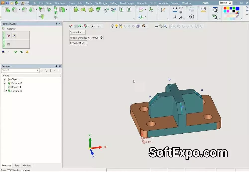
On the design side, new mold‑specific tools such as chord‑length‑based rounds, hole‑by‑screw‑size helpers, and smarter Burn Body operations line up with how mold designers actually think about fasteners and burn areas. Multi‑view spacing tweaks, smoother blends, and better tangent control help Cimatron CAD users get to “manufacturable” faster on ugly imported geometry.
Cimatron 2024 also tightens its link to real tools: integration with CoroPlus Tool Library and TDM means your virtual tool assemblies in Cimatron CAM can mirror what is actually racked in the crib, instead of living as random cutters in someone’s head.
1) Start from the model, not from the machine.
Pull in native CAD or clean STEP/IGES, then use Cimatron CAD tools to build the full mold or die: parting surfaces, splits, cores, cavities, sliders, lifters, ejectors, cooling, and standard components. The sooner you make Cimatron the single home of the tooling model, the less time you spend chasing geometry later.
2) Lock in electrodes while the design is still hot.
As soon as burn areas are clear, derive electrodes directly in Cimatron electrode design. Define gaps, directions, and holder data, then let the system track naming, positions, and EDM reports instead of managing it in spreadsheets.
3) Push the same data into Cimatron CAM.
With the assembly stable, switch to Cimatron CAM programming. Define stock, set coordinate systems, then apply your shop’s go‑to 2.5D and 3D strategies for roughing, rest‑roughing, and finishing, using libraries tuned for your machines and materials.
4) Use NC Process like a playbook.
Bundle operations into NC Process templates for common patterns: standard cavity blocks, lifter pockets, core inserts, and electrodes. This is where Cimatron CAM goes from “one‑off” programming to repeatable, documented processes juniors can run without wrecking a mold.
5) Simulate, post, and keep the loop tight.
Simulate toolpaths, check for gouges and collisions, then postprocess for the actual controllers on the floor. When changes land from the customer, update the Cimatron CAD model and let associativity drive updates back through Cimatron CAM instead of starting over.